Brushless Motor with Resonant Tuning
Title: Brushless Motor
Filed: 19-03-2009
Number: GB0904679.8
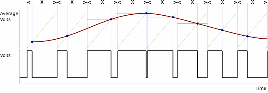 Figure 1
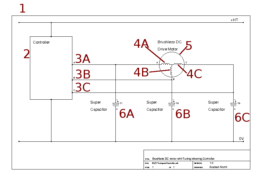 Figure 2
The present invention relates to a brushless motor.
It is well known to provide a brushless motor having three or three sets of inductors which are each driven by a phase of a three phase synthesised AC supply of electricity.
The AC supply of electricity is typically generated by a controller circuit which delivers, typically between 0 and 300V, a synthesised sine wave using pulse width modulation signal as shown in Figure 1.
The output is the average voltage over the fixed time period "X" between the first leading edge and the next.
The longer the input is in the high state (the pulse width) the higher the average voltage on the output.
The invention seeks to provide an improved brushless motor.
According to the present invention there is provided a brushless motor comprising:
a) three or three sets of inductors each connected to a phase of a three phase synthesised AC supply of electricity formed by a PWM waveform, and
b) a capacitor for each inductor or each set of inductors, in use the pairs of capacitors and pairs of inductors forming a resonant circuit for each AC phase thereby increasing the magnetic flux density provided by the inductors.
Preferably the synthesised AC supply is generated by a controller in which each phase delivers a voltage across a first positive value and a second lower neutral or lower second positive voltage value.
Preferably each capacitor is connected across a first positive value and a second lower neutral or lower second positive voltage value.
The invention also relates to a method of driving the inductors of a brushless motor powered by a synthesised AC supply of electricity formed by a PWM waveform, comprising forming a resonant circuit with a capacitor with each inductor.
Preferably pairs of capacitors and pairs of inductors form a resonant circuit for each AC phase.
Preferably the synthesised AC supply is generated by a controller in which each phase delivers a voltage across a first positive value and a second lower neutral or lower second positive voltage value.
Preferably each capacitor is connected across a first positive value and a second lower neutral or lower second positive voltage value.
Preferably the motor has three or three sets of inductors and the AC supply is a three phase supply with one phase for each or each set of inductors.
An embodiment of the invention will now be described with reference to Figure 2 of the accompanying drawings showing a schematic circuit diagram.
Referring to Figure 2, there is shown a schematic circuit diagram of a brushless motor 1.
Motor 1 is driven by a DC source across a positive voltage (+HT), e.g. 300V. and neutral (0V).
A controller 2 generates a three phased synthesised AC supply of electricity on three lines 3A, 3B, 3C.
Each phase is a PWM waveform of the type as shown in Figure 1.
Each line 3A, 3B, 3C is respectively connected to three inductors 4A, 4B, 4C in the drive unit 5.
Three capacitors 6A, 6B, 6C are respectively connected to each inductor between lines 3A, 3B, 3C and neutral (0V).
In use the pairs of capacitors and pairs of inductors forming a resonant circuit for each AC phase thereby increasing the magnetic flux density provided by the inductors.
This increases the power output for the motor.
Thus inductor 4A and capacitor 6A and inductor 4B and capacitor 6B form a resonant circuit for the AC phase on line 3A, inductor 4B and capacitor 6B and inductor 4C and capacitor 6C form a resonant circuit for the AC phase on line 3B, inductor 4C and capacitor 6C and inductor 4A and capacitor 6A form a resonant circuit for the AC phase on line 3C.
Because the controller always generates a positive voltage value in each of its phases (i.e. the voltage does not ever become negative), super capacitors may be used which do not normally accept a reverse polarity.
Instead of the motor being supplied by a DC source across a positive voltage (+HT), e.g. 300V, and a neutral (0V), the DC source could be across a positive voltage (+HT), e.g. 300V, and a lower positive value e.g. 20V.
The values of the capacitors and the inductors are chosen to create a resonance based on the frequency of the time base "X".
Also although drive unit 5 is shown with three inductors 4A, 4B, 4C, these inductors could be three sets of inductors as is well known in the art.
The invention also relates to a method of driving the inductors of a brushless motor powered by a synthesised AC supply of electricity formed by a PWM waveform, comprising forming a resonant circuit with a capacitor with each inductor.
Preferably pairs of capacitors and pairs of inductors form a resonant circuit for each phase.
Preferably the motor has three or three sets of inductors and the AC supply is a three phase supply with one phase for each or each set or inductors.
The invention may take a form different to that specifically described above.
Further modifications will be apparent to those skilled in the art without departing from the scope of the present invention.
CLAIMS
1. A brushless motor comprising:
a) three or three sets of inductors each connected to a phase of a three phase synthesised AC supply of electricity formed by a PWM waveform, and
b) a capacitor for each inductor or set of inductors, in use the pairs of capacitors and pairs of inductors forming a resonant circuit for each AC phase thereby increasing the magnetic flux density provided by the inductors.
2. A brushless motor according to claim 1, wherein the synthesised AC supply is generated by a controller in which each phase delivers a voltage across a first positive value and a second lower neutral or lower secon positive voltage value.
3. A brushless motor according to claim 2, wherein each capacitor is connected across the first positive value and the second lower neutral or lower positive voltage value.
4. A method of driving the inductors of a brushless motor by a synthesised AC supply of electricity formed by PWM waveform, comprising forming a resonant circuit with a capacitor with each inductor.
5. A method according to claim 4, wherein pairs of capacitors and pairs of inductors form a resonant circuit for each AC phase.
6. A method according to claim 4 or 5, wherein the synthesised AC supply is generated by a controller in which each phase delivers a voltage across a first positive value and a second lower neutral or lower secon positive voltage value.
7. A method according to claim 4, 5 or 6, wherein each capacitor is connected across the first positive value and the second lower neutral or lower secon positive voltage value.
8. A method according to any of claims 4 to 7, wherein the motor has three or three sets of inductors and the AC supply is a three phase supply with one phase for each or each set of inductors.
9. A brushless motor substantially as hereinbefore described with reference to and as shown in the accompanying drawings.
10. A method of driving the inductors of a brushless motor powered by a synthesised AC supply of electricity formed by a PWM waveform substantially as hereinbefore described.
ABSTRACT
The invention relates to a brushless motor 1.
Three inductors 4A, 4B, 4C are each connected to a phase 3A, 3B, 3C of a three phase synthesised AC supply of electricity formed by PWM waveform.
A capacitor 6A, 6B, 6C is provided for each inductor.
In use the pairs of capacitors and pairs of inductors for a resonant circuit for each AC phase thereby increasing the magnetic flux density provided by the inductors.
The invention also extends to a method of driving the inductors of a brushless motor.
