Decoupled Gas Turbine Generator
Title: Decoupled Gas Turbine Generator
Filed: 05/02/2010
Number: GB1001921.4
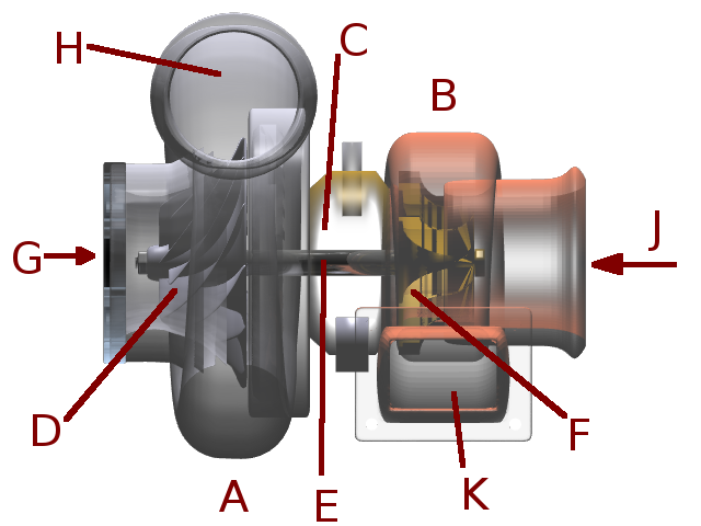 Figure 1
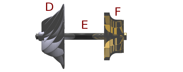 Figure 2
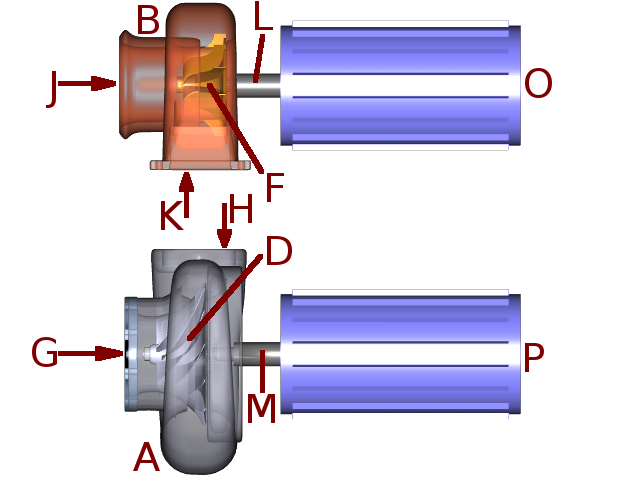 Figure 3
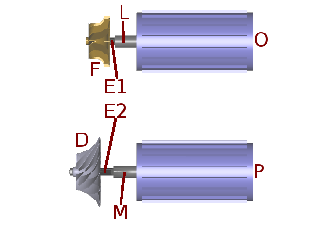 Figure 4
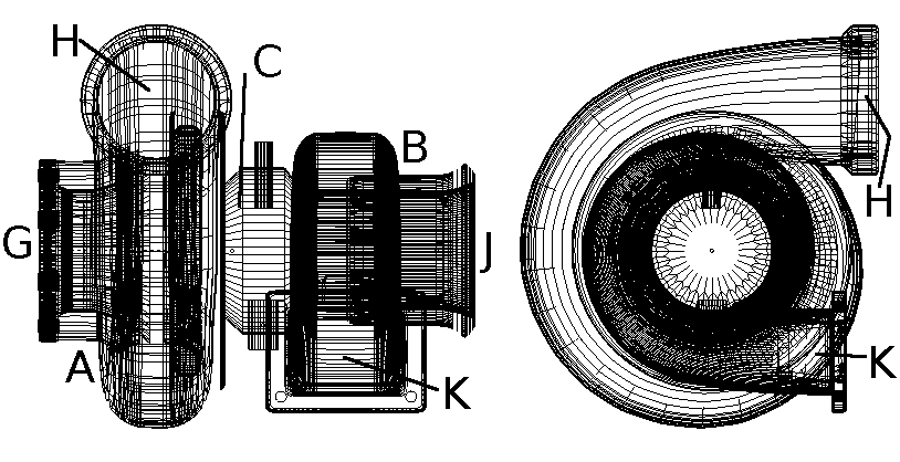 Figure 5
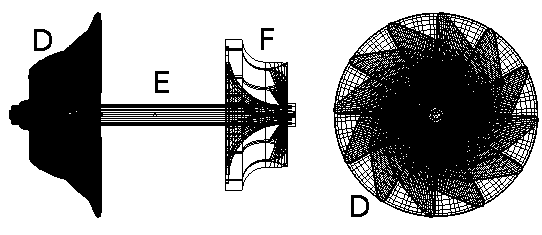 Figure 6
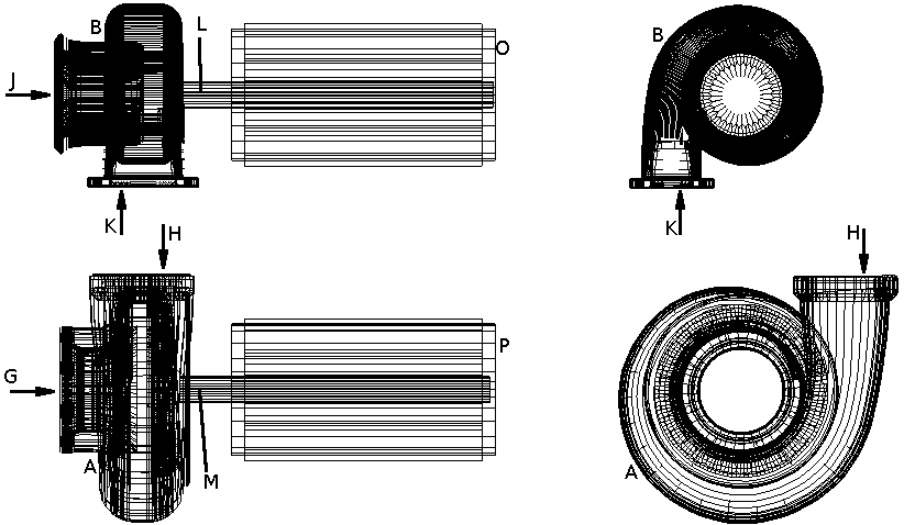 Figure 7
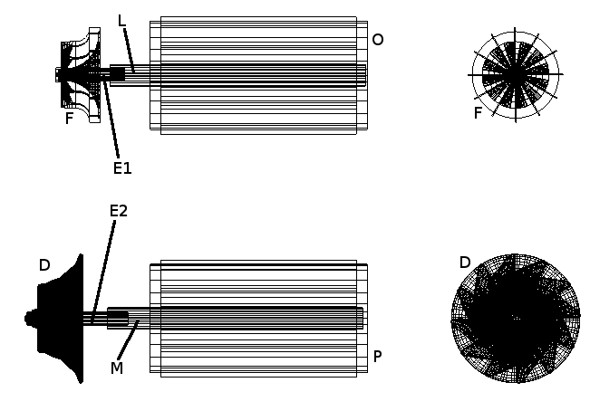 Figure 8
The present invention relates to a gas turbine engine.
Background
It is well known to provide a gas turbine engine comprising an air compressor and a turbine connected directly to the compressor via a shaft.
It is also well known in the art to adapt an automotive turbo, normally used to boost the efficiency and power of an automotive piston engine, into a gas turbine engine by including a combustion chamber.
For the avoidance of doubt, the term "gas" in the phrase "gas turbine" refers to the way the engine burns fuel to produce high-pressure, high-velocity gas and does not refer to the use of "gas" as a fuel for the engine.
Automotive Turbo
The automotive turbo is used as the compressor and turbine of a gas turbine engine by those competent in the art.
�There now follows a description of the current mechanical design of an automotive turbo shown in figures 1, 2, 5 and 6 of the attached diagrams.
Figures 1, 2, 5 and 6 show a mechanical model of an automotive turbo which is well known.
Figures 5 and 6 show the same model as figures 1 and 2 respectively but as a wire-frame model containing the front and side elevations for monochrome printing.
Figure 5 has bearing C, compressor fan D, shaft E and turbine fan F removed for clarity.
Figure 2 and 6 show the internal rotating shaft with the compressor fan and turbine fan attached, but with the fixed housings and bearings removed from view for clarity.
Referring to figures 1, 2, 5 and 6 of the attached diagrams, these show the mechanical arrangement of a compressor A and turbine B connected via a shaft E through a bearing C as is the standard design for an automotive turbo.
The compressor A is comprised of the rotating compressor fan D and the fixed ducting housing which has an intake G and an outlet H.
The turbine B is comprised of the rotating turbine fan F and the fixed ducting housing which has an inlet K and an outlet (exhaust) J.
To form a full gas turbine engine from this arrangement one would attach a combustion chamber between outlet H on the compressor and inlet K on the turbine.
This combustion chamber would add fuel to the compressed air coming from compressor A in a continuously burning chamber and the accelerated burned gases would be expelled through turbine B via inlet K.
This would cause the turbine fan to spin thus powering the compressor fan D via the connecting shaft E.
The Invention
The invention seeks to provide an improved gas turbine engine for use as a generator of electricity.
According to the present invention there is provided a decoupled gas turbine generator comprising:
a) a compressor,
b) a motor attached to the shaft of the compressor fan,
c) a turbine, and
d) a generator attached to the shaft of the turbine fan.
Preferably the compressor and turbine are of the centrifugal type.
Preferably the compressor and turbine are connected to the combustion chamber at opposite ends of the chamber.
Preferably the compressor and turbine are of similar size.
Preferably the compressor fan is connected directly to the shaft of the motor.
Preferably the turbine fan is connected directly to the shaft of the generator.
The invention also relates to a method of producing electricity from a combustible liquid or gas.
Preferably the fuel used in the combustion chamber is hydrogen, gasoline or propane.
Preferably the output from the generator will be a higher voltage than that required by the motor attached to the compressor.
Preferably the output from the generator will be electrically connected to the motor on the compressor.
An embodiment of the invention will now be described with reference to figures 3, 4, 7 and 8 of the accompanying drawings showing a mechanical model.
Figures 7 and 8 show the same model as figures 3 and 4 respectively but as a wire-frame model containing the front and side elevations for monochrome printing.
Figure 7 has compressor fan D, shafts E1 and E2 and turbine fan F removed for clarity.
Figures 4 and 8 shows the same mechanical model as figure 3 and 7 respectively, but with the fixed housings of the compressor and turbine removed for clarity.
Referring to figures 4 and 8:
The compressor fan D is attached to the motor shaft M via shaft E2.
The turbine fan F is attached to the generator shaft L via shaft E1.
Referring to figures 3 and 7, the generator O is attached to the turbine B and the motor P is attached to the compressor A.
The motor P spins the compressor fan D thus causing the compressor to draw in air via inlet G and expels the air under pressure via outlet H.
This is then mixed with fuel in the combustion chamber and burned in a similar way fuel-air mixture would be burned in piston or gas turbine engines as is well known in the art.
This burning fuel-air mixture expands and is ejected from the combustion chamber into inlet K of turbine B.
This causes the turbine fan F to spin which removes energy from the fast moving ejected gas, and the gas is expelled via the turbine outlet J.
Since the turbine fan F is connected to the generator O, this causes the generator O to spin thus generating electricity.
The generator O will provide power for the motor P thus causing it to turn and completing the energy transfer cycle.
The invention also related to a method of starting a gas turbine engine.
Preferably the motor can also be connected to batteries to spin the compressor independently of the turbine.
The motor P can be connected to batteries to spin the compressor without the turbine.
This provides a mechanism for starting the decoupled gas turbine generator.
Since the electricity generated from generator O will be considerably more than required by motor P to drive the compressor, this excess electricity will be used as an electric source of power.
CLAIMS
1. A decoupled gas turbine generator comprising:
a) a compressor,
b) a motor attached to the shaft of the compressor fan,
c) a turbine, and
d) a generator attached to the shaft of the turbine fan.
2. A decoupled gas turbine generator according to claim 1, wherein the turbine is connected to a generator.
3. A decoupled gas turbine generator according to claim 1 and 2, wherein the turbine powers a generator.
4. A decoupled gas turbine generator according to claim 1, 2 and 3, wherein the motor powers the compressor fan within the compressor.
5. A decoupled gas turbine generator according to claim 1 to 4, wherein the motor draws power directly or indirectly from the generator.
6. A decoupled gas turbine generator substantially as hereinbefore described with reference to and as shown in figures 3, 4, 7 and 8 of the accompanying drawings.
7. A method of generating electricity using a gas turbine engine where a compressor is not mechanically connected to a turbine in the same engine.
ABSTRACT
The invention relates to a gas turbine engine.
Normally in the art a compressor fan is powered directly from a turbine fan in the same engine via a connecting shaft.
In this invention the compressor fan D is powered by motor P, which is powered by generator O which is powered by the turbine fan F.
This invention provides a method of generating an external electricity supply directly from generator O.
The invention also extends to a method of generating electricity from a gas turbine engine.
The invention also extends to a method of starting a gas turbine engine.
