Brushless Motor without Permanent Magnets
Title: Brushless Motor without Permanent Magnets
Filed: 05/02/2010
Number: GB1001919.8
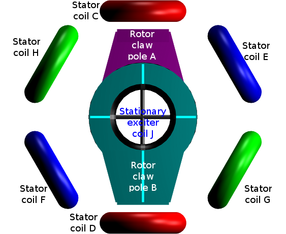 Figure 1
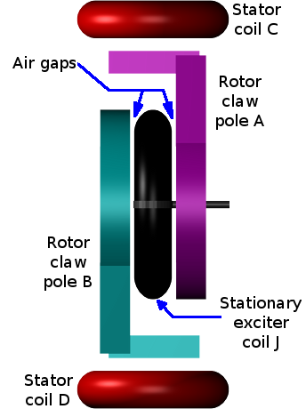 Figure 2
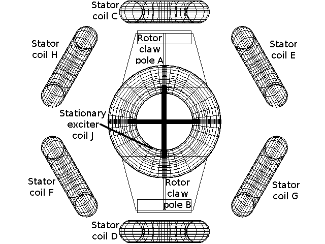 Figure 3
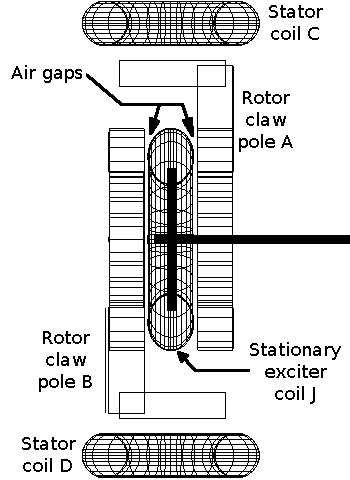 Figure 4
The present invention relates to a brushless motor.
Background
It is well known to provide a brushless motor having sets of electromagnetic coils which are each driven by a phase of a multi phase AC supply of electricity.
In Runner Type Brushless Motor
It is also well known the brushless motor has either a central permanent magnet or permanent magnets which comprise the rotating component of the motor.
This central permanent magnet or permanent magnets would normally be connected to the output shaft of the motor.
Around the central permanent magnet or permanent magnets would be the sets of fixed electromagnetic coils.
The sets of fixed electromagnetic coils would be fixed to the inside of the case of the motor housing.
This type of brushless motor mechanical arrangement is normally known as an "in runner".
Out Runner Type Brushless Motor
A well known variation on the above described would be a brushless motor with the static coils fixed onto a central shaft or tube.
Around this static central shaft or tube would be a drum mounted on another shaft in line with the static central shaft or inside the static central tube.
This drum would have permanent magnets attached to the inside rim in close proximity to the static coils fixed onto the central shaft or tube.
The drum with the permanent magnets would rotate around the outside of the static coils in the same way the central permanent magnet or permanent magnets would rotate inside the "in runner" motor described above.
The arrangement with permanent magnets that rotate around the outside of the static coils is normally known as an "out runner".
Automotive Alternator
It is also well known that the use of a non-permanent magnet core in generator design is used in a common automotive battery charger, known as an alternator.
In the alternator this core has an electromagnet fixed onto a shaft with the rotor plates and connected to a DC supply via slip rings and brushes.
The Invention
This invention as described herein for the in-runner type brushless motor, would equally apply to the out-runner with modified mechanical arrangement by those skilled in the art.
This invention as described herein for a two pole rotor brushless motor, would equally apply to a multi-pole rotor brushless motor with modified mechanical arrangement by those skilled in the art.
The invention seeks to provide an improved brushless motor using technology adapted from the automotive alternator.
According to the present invention there is provided a brushless motor comprising:
a) outer sets of coils connected to a controller unit,
b) a central coil connected to a DC supply of electricity, and
c) a pair of plates made from magnetically conductive material (e.g. steel).
Preferably the outer sets of coils are three or three sets of coils.
Preferably the outer sets of coils are each connected to a phase of a three phase AC supply of electricity.
Preferably the phases of AC supply are synthesised using pulse width modulation from a controller connected to a DC supply of electricity.
Preferably the outer sets of coils are fixed to the inside of the motor housing.
Preferably the central coil is fixed to the motor housing via a shaft.
The invention also relates to a method of extracting mechanical output from an electric motor.
Preferably the pair of plates would be affixed to a non-magnetic gimbal (or cage arrangement).
Preferably the gimbal is fixed to the motor output shaft.
The embodiment of the invention will now be described with reference to Figure 1, 2, 3 and 4 of the accompanying drawings showing two views of a mechanical model.
Figure 1 shows the front elevation of the mechanical model, and Figure 2 shows a side elevation of the same model with static coils E, F, G and H removed for clarity.
Figures 3 and 4 are copies of figures 1 and 2 respectively the only difference being they are rendered as wire-frame models for monochrome document purposes.
Static coils C and D are electrically connected to form two opposite poles of an electromagnet.
This would be connected to one phase of the AC supply from the controller.
Likewise, static coils E and F form two opposite poles of a second electromagnet connected to a second phase of the AC supply from the controller.
Likewise, static coils G and H form two opposite poles of a third electromagnet connected to a third phase of the AC supply from the controller.
The controller energises each electromagnet, comprising of 2 static coils, in sequence to produce a rotating magnetic field.
This rotating magnetic field appears as if there was an imaginary magnet rotating inside the motor around the center and in the same plane as the static coils.
This is known in the art as "Space Vector Modulation".
The stationary exciter coil J is energised with a DC supply to provide a fixed magnetic field.
Referring to figure 2, this magnetic field would appear with one pole (e.g. north) to the left of the diagram and the other pole (e.g. south) to the right.
Referring to figure 1, the field would be perpendicular to the page.
The stationary exciter coil J would magnetise the rotor plates A and B in sympathy to produce a field at the narrow end of the rotor plates nearest the static coils.
The net effect is to produce a single magnet comprising the stationary exciter coil J and the rotor plates A and B which replaces the permanent magnet one would normally find in a normal in-runner brushless motor in the art.
CLAIMS
1. A brushless motor comprising:
a) sets of coils connected to a controller unit,
b) a central coil connected to a DC supply of electricity, and
c) a pair of plates made from magnetically conductive material.
2. A brushless motor according to claim 1, wherein the central coil is stationary.
3. A brushless motor according to claim 1 and 2, wherein the pair of plates are mechanically separate from the central coil.
4. A brushless motor according to claim 1, 2 and 3, wherein the pair of plates rotate inside a set of coils.
5. A method according to claim 1 to 4, of magnetising rotating plates using a fixed coil.
6. A method according to claim 5, of electrically magnetising rotating plates without using brushes.
7. A brushless motor substantially as hereinbefore described with reference to and as shown in the accompanying drawings.
8. A method of electrically magnetising rotating plates without using brushes substantially as hereinbefore described.
ABSTRACT
The invention relates to a brushless motor.
The central core would comprise of rotor plates A and B, and stationary exciter coil J.
The rotor plates A and B would rotate inside the motor magnetised by stationary exciter coil J.
The rotor plates A and B together with stationary exciter coil J act in a similar manner to a permanent magnet within a brushless motor as found in the art.
The invention also extends to a method of using an electromagnetic rotor in a brushless motor without using brushes.
